Product description
Specifications:
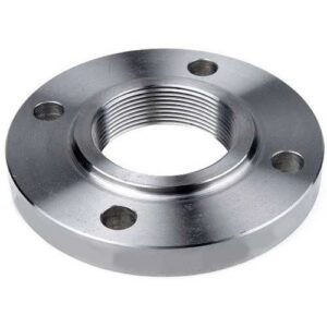
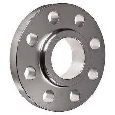
| Type | : | SO Forged Flange |
| Size | : | ½” (15 NB) to 48″ (1200NB) |
| Standard | : | ANSI B16.5, ANSI B16.47, ANSI B16.36, ANSI B16.48, BS 4504, EN1092, UNI 2277/2278, DIN, JIS, SABS1123, GOST-12820 |
| Class | : | 150 LBS, 300 LBS, 600 LBS, 900 LBS, 1500 LBS, 2500 LBS, DIN Standard ND-6,10, 16, 25, 40 Etc. |
| DIN | : | DIN2527, DIN2566, DIN2573, DIN2576, DIN2641, DIN2642, DIN2655, DIN2656, DIN2627, DIN2628, DIN2629, DIN 2631, DIN2632, DIN2633, DIN2634, DIN2635, DIN2636,DIN2637, DIN2638, DIN2673 |
| BS | : | BS4504 , BS4504, BS1560, BS10 |
| In Form | : | SORF, WNRF, BLRF, SWRF, LAP Joint, Threaded, Reducing, Spectacle, etc |
| Specialize | : | As per drawing |
| Coating/Surface Treatment | : | Anti-rust Paint, Oil Black Paint, Yellow Transparent, Zinc Plated, Cold and Hot Dip Galvanized |
| Connection Type | : | Ring Type Joint, Lap-Joint Face, Raised Face, Flat Face, Large Male-Female, Small Male-Female, Large |
| Tongue & Groove, Small Tongue & Groove | ||
| Flange Face Type | : | Flat Face (FF), Raise Face (RF), Ring Joint (RJT) |
| Dimensions | : | ANSI B16.5, ANSI B16.47 Series A & B, MSS SP44, ASA, API-605, AWWA, Custom Drawings |
| Packing | : | No Fumigate or Fumigate Plywood/Wood Pallet or Case |
| Usage | : | Oil Field, Offshore, Water System, Shipbuilding, Natural Gas, Electric Power, Pipe Projects etc. |
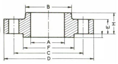
Dimensions:
| Drilling | |||||||||
|---|---|---|---|---|---|---|---|---|---|
| Nominal Bore | Dia. (D) |
Thick. (E) |
Dia. (F) |
Dia. (B) |
Dia. (A) |
Height1 (H) |
Nbr | Holes | Dia. (C) |
| 1/2″ | 90 | 9.6 | 35.05 | 30 | 22.2 | 14 | 4 | 15.87 | 60.3 |
| 3/4″ | 100 | 11.2 | 42.93 | 38 | 27.7 | 14 | 4 | 15.87 | 69.9 |
| 1″ | 110 | 12.7 | 50.80 | 49 | 34.5 | 16 | 4 | 15.87 | 79.4 |
| 1 1/4″ | 115 | 14.3 | 63.50 | 59 | 43.2 | 19 | 4 | 15.87 | 88.9 |
| 1 1/2″ | 125 | 15.9 | 73.15 | 65 | 49.5 | 21 | 4 | 15.87 | 98.4 |
| 2″ | 150 | 17.5 | 91.95 | 78 | 61.9 | 24 | 4 | 19.05 | 120.7 |
| 2 1/2″ | 180 | 20.7 | 104.65 | 90 | 74.6 | 27 | 4 | 19.05 | 139.7 |
| 3″ | 190 | 22.3 | 127.00 | 108 | 90.7 | 29 | 4 | 19.05 | 152.4 |
| 3 1/2″ | 215 | 22.3 | 139.70 | 122 | 103.4 | 30 | 8 | 19.05 | 177.8 |
| 4″ | 230 | 22.3 | 157.22 | 135 | 116.1 | 32 | 8 | 19.05 | 190.5 |
| 5″ | 255 | 22.3 | 185.67 | 164 | 143.8 | 35 | 8 | 22.22 | 215.9 |
| 6″ | 280 | 23.9 | 215.90 | 192 | 170.7 | 38 | 8 | 22.22 | 241.3 |
| 8″ | 345 | 27.0 | 269.75 | 246 | 221.5 | 43 | 8 | 22.22 | 298.5 |
| 10″ | 405 | 28.6 | 323.85 | 305 | 276.2 | 48 | 12 | 25.40 | 362.0 |
| 12″ | 485 | 30.2 | 381.00 | 365 | 327.0 | 54 | 12 | 25.40 | 431.8 |
| 14″ | 535 | 33.4 | 412.75 | 400 | 359.2 | 56 | 12 | 28.57 | 476.3 |
| 16″ | 595 | 35.0 | 469.90 | 457 | 410.5 | 62 | 16 | 28.57 | 539.8 |
| 18″ | 635 | 38.1 | 533.40 | 505 | 461.8 | 67 | 16 | 31.75 | 577.9 |
| 20″ | 700 | 41.3 | 584.20 | 559 | 513.1 | 71 | 20 | 31.75 | 635.0 |
| 24″ | 815 | 46.1 | 692.15 | 663 | 616.0 | 81 | 20 | 34.92 | 74 |
Note: 1,6mm raised face not included in the E & H dimensions